Launchpad and Controllers
A launchpad is a structure that provides vertical support for a rocket before liftoff and at the same time provides a means of ignition for the rocket motor. In the simplest of forms, it consists of a large flat base and a long vertical steel rod mounted perpendicularly to it. The rocket consists of a launch lug mounted on the outer edge of the rocket at a point free from any vertical constraints. The launch lug is a short hollow cylindrical tube.
To have a safe, predictable flight, the model rocket must be held in position before launch and guided during the first fraction of a second of flight until it is going fast enough for its fins to keep it flying in the proper direction. The device performing this function should be designed to aim the rocket straight up. It may be made adjustable so that the model can be “aimed” either vertically or within 30° to any side of vertical to correct for wind conditions. The launch lug on the model fits over the rod, keeping the rocket straight on the rod. By the time the model rocket’s launch lug leaves the launch rod the rocket is going fast enough for its fins to provide adequate guidance to keep it moving in the desired direction.
 |
| 3D Printed Launchpad, stl from Thingiverse |
The second function a launch system must perform is to provide adequate electrical current to cause engine ignition. The electrical current accomplishes engine ignition by heating the igniter which produces enough heat to cause the solid propellant to ignite. The igniter must be placed with its bend all the way to the bottom of the nozzle and firmly in contact with the propellant. The igniter must be held firmly in place with an igniter plug so that the weight of the micro-clips and wire will not pull it away from the propellant.
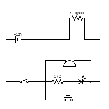 |
| Circuit Diagram of 2nd Gen Launch Controller |
General common sense states that a rocket must be ignited from a safe distance. This is usually accomplished by connecting the ignitors using a set of micro clips which is in turn connected to a launch controller by a pair of long wires. But this method has a few drawbacks. Greater the length of the wire, the higher the resistance produced, and hence a higher capacity battery must be used to compensate for the lost current.
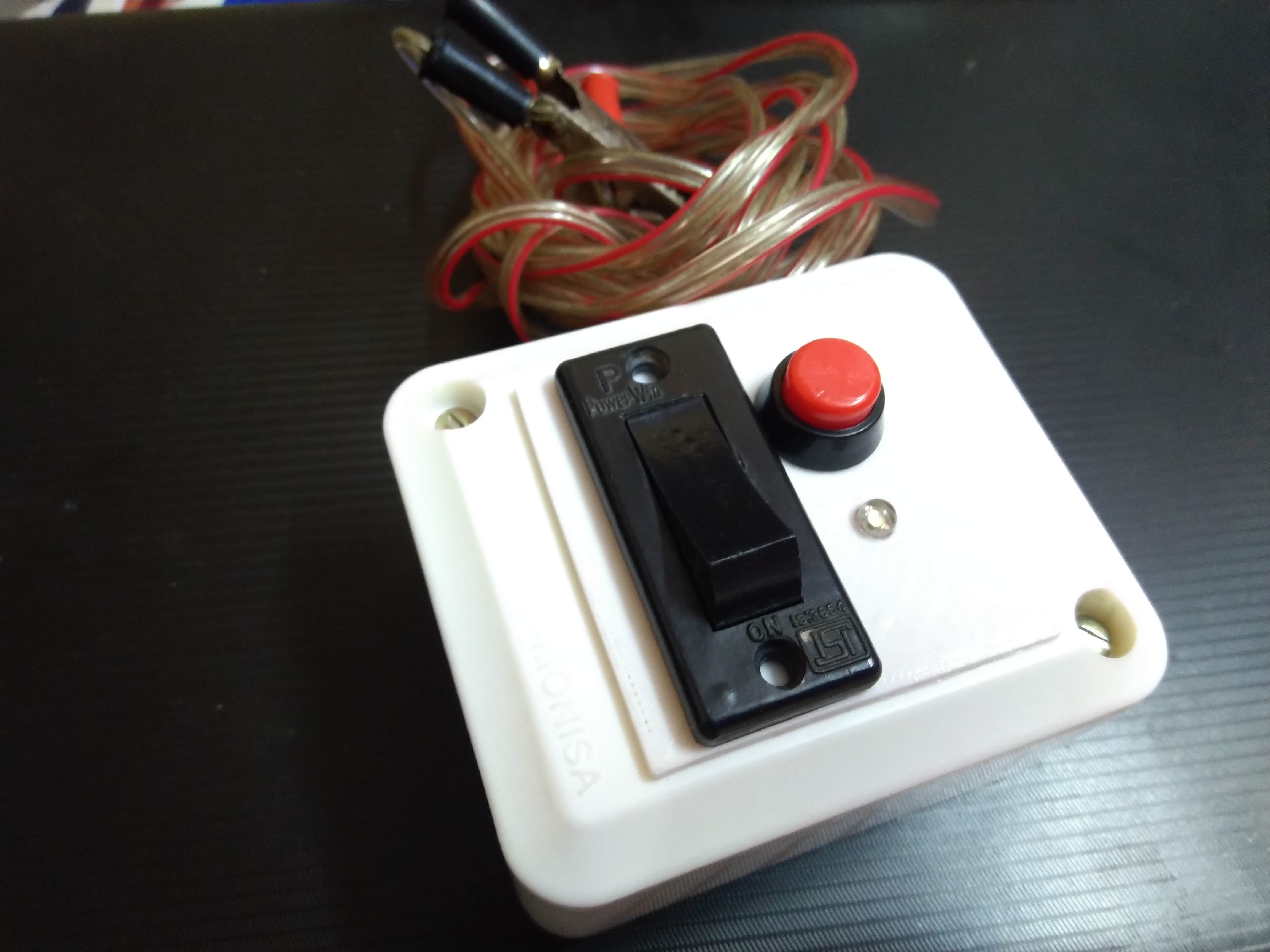 |
| 2nd Gen Launch Controller |
However, in the next iteration, it was decided to completely eliminate the wires and replacing it with a wireless system. The launchpad, the ignition system, the battery and the wireless system subcomponents are assembled in a single unit. The remote control mechanism is achieved by the use of an android application installed in a suitable smartphone. Hence the rocket can be easily and safely ignited from a distance of up to 10 meters.
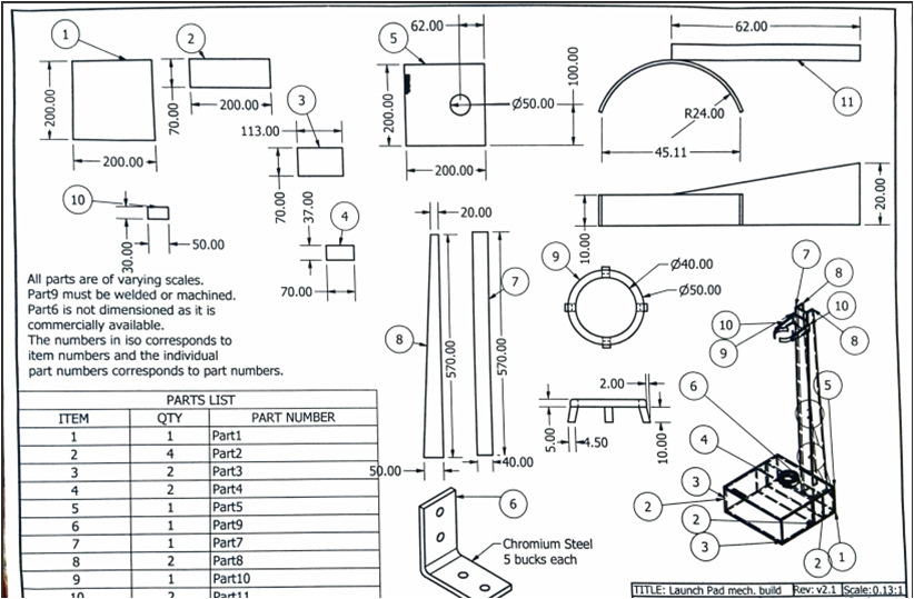 |
| Part Drawing of 3rd Gen wireless Launch Controller |
The material we used for the construction of the frame is Aluminum Composite Sheet. This material is easy to work with in terms of cutting and drilling. It consists of a container-like structure that acts as a base and as housing for the 12v 7.5Ah battery. A tower-like structure protrudes from the center of one end of the base. The top end of the tower houses the pivotable grab arms. The top cover of the base houses the glowplug mounting and the 8mm Aluminum Launch Rod. A bore in the top cover allows for the deflection of the exhaust gases from the rocket. A protrusion from the base is used to mount the control electronics and the BlueTooth radio.
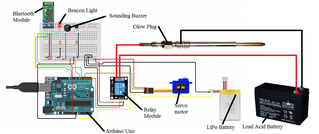 |
| Electrical Schematic of 3rd Gen wireless Launch Controller |
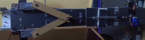 |
| Launchpad Grab Arm Actuation Mechanism |
The initial idea was to use each arm with an independent servo for its control. But since the servo motor uses a higher current that passes through the arduino, we designed a mechanism that enables the use of only a single servo motor to actuate both the arms. This mechanism has two degrees of freedom according to Grubbler’s Criteria.
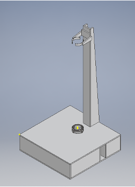 | 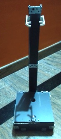 |
| Launchpad CAD Render | Launchpad Assembly |